G1739
Drip Irrigation Design and Management Considerations for Windbreaks
This publication discusses drip irrigation, one of the most commonly used methods to irrigate windbreaks.
Suat Irmak, Water Resource Engineer
- Irrigating Windbreaks and System Layout
- System Design
- Selecting an Emitter
- Selecting Pipe Sizes
- Design Pressure
- Installation
- System Operation
- Cost
- Acknowledgment
|
A windbreak, or shelterbelt, usually is made up of one or more rows of trees or shrubs planted in such a manner as to provide shelter from the wind and to prevent soil erosion. Properly designed and placed windbreaks can help to slow, direct and block winds, resulting in many benefits to farmers, ranchers and rural residents. A properly designed tree windbreak or shelterbelt provides protection for livestock, crops and farmsteads. A windbreak also can reduce the energy exchange between the indoor and outdoor climate through reduced wind speed resulting in significant energy savings for heating a rural residence.
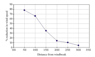
Windbreak height (H) is the most important factor used to determine the distance downwind that is protected by a windbreak. The relationship between the H and the percentage reduction in wind speed will vary with the windbreak type and the distance between the trees. The maximum reduction in wind speed is observed at the location closest to the windbreak; at distances of 25 to 30 times H wind speed usually is reduced by less than 10 percent (Figure 1; Data from: Iowa State University Publication No: PM-1716, 1997). For example, if the windbreak is 20 feet tall, the wind speed is reduced by about 80 percent at a distance of 5H (100 ft). At a distance of 30H (600 ft), the reduction in wind speed is only 4 percent. There is a small reduction in wind speed up to one to four times H on the upwind side of a windbreak. The taller the windbreak, the greater the zone of protection. The percent of reduction in wind speed is relatively constant and is mostly independent of wind velocity at greater distances. The density of a windbreak will affect the percent reduction of wind speed. Density is the ratio of the solid portion of a windbreak to the total area of the barrier. Very dense windbreaks reduce wind speed in the zero to 10H zone more than less dense windbreaks.
Irrigating Windbreaks and System Layout
|
Irrigation can help establish successful tree plantings and help them become effective windbreaks at an earlier date than non-irrigated trees. Drip (trickle) irrigation is one of the most commonly used methods to irrigate windbreaks. Due to the nature of the windbreak orientation (rows of trees), drip irrigating windbreaks is more feasible than other methods and can help to reduce soil evaporation, requiring less water application. Surface drip irrigation is commonly used for windbreaks.
The heart of a drip irrigation system is the emitter. It is designed to release water at a rate so slowly that the emitters tend to drip or trickle, hence the name. The water application rate should be less than the infiltration rate of the soil to prevent runoff. This allows the water to be precisely applied only at the base of each tree, where it is needed.
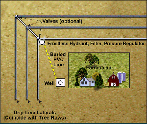
The emitter is installed on a lateral which is a black polyethylene pipe either 1/2 or 3/4 inch in diameter, depending on the length requirement. Laterals are laid along the tree rows (Figure 2). A number of laterals can be tied together with a manifold of the same size pipe for convenience. This manifold is connected to the main water supply by a frostproof hydrant and filter, with a pressure regulator in between them.
Water is conveyed from a water source to the hydrant by a buried PVC pipe. Temporary supply lines, such as garden hoses, may prove to be more of a nuisance and more expensive over the long run than permanent lines. It is necessary to use a filter of extremely fine mesh (50 mesh or finer; 100 mesh for pressure sensitive emitters) at the hydrant to avoid clogging the emitters. A paper element sediment filter ordered from a department store catalog works well. Filters also are available from drip irrigation dealers. If the main PVC line is buried it needs to be buried below the frost depth. In Nebraska, the frost depth will vary with location, but burying the PVC pipe below 3.0 feet will usually provide protection from frost.
The emitters must operate at a specific pressure (15 to 25 psi), so a pressure regulator or a pressure gauge and a small globe valve is required to control the pressure properly. These items can be obtained from a hardware store or from companies that supply irrigation equipment. They can be connected to the hydrant with a polyethylene pipe that is used as a supply line to the laterals. Drip irrigation suppliers have a wide variety of fittings that are ideal for installing a drip irrigation system.
System Design
The first step is to map the windbreak with a sketch (Figure 2) that includes the following:
- Length of each lateral.
- Species planted in each row.
- Location of water supply and supply line.
- Location of hydrant and manifold.
- Difference in elevation between the highest and lowest point in each lateral.
Selecting an Emitter
An emitter is designed to put out a specific flow rate. Most commonly, there is a choice between 0.5, 1.0, 1.5, or 2.0 gallons per hour. The 1.0 gph emitter is recommended because the flow rate is adequate for the purpose but small enough to extend limited water supplies and avoid excessive pipe friction problems. Emitters with an output rate of 0.5 gph can also be used. In circumstances where the windbreak must be watered quickly, larger flow rates can be used. Caution: Higher flow rates will reduce the allowable length of laterals that can be used due to excessive friction losses that cause pressure variations in the laterals. A drip irrigation design expert should be consulted under these circumstances.
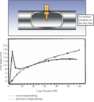
The flow rate variation of typical emitters with different lateral water pressure is shown in Figure 3. This example shows that a pressure compensating emitter is not 100 percent effective, but does suppress major flow fluctuations as compared to the non compensating emitter. Pressure compensating emitters try to provide a constant flow rate, through a diaphragm embedded into the emitter, under varying pressure. A pressure compensating emitter with a self-flushing capability is recommended. This type of emitter presents the fewest design problems and will not clog as often as other types. The maximum length of lateral that can be used with pressure compensating emitters is shown in Table I. Allowable lateral lengths and their influence on the selection of an emitter will be discussed later.
Many companies manufacture emitters that fulfill the requirements previously outlined and have wide product distribution. If the product is suitable, available and meets the specifications, it can be used. However, the least expensive emitter that will do the job is desirable (as long as there is good dealer reliability) to keep the system’s cost down. A pressure compensating emitter that is self-flushing will greatly simplify the design and operation of the drip irrigation system and is recommended even if the price is slightly higher.
|
||||||||||||||
Selecting Pipe Sizes
A drip system can be adapted to variable water supplies. Calculation of the water requirement is simple. Multiply the number of trees to be irrigated by the gallons per hour delivered by an emitter. Divide by 60 to determine the gallons per minute. [Example: (120 trees x 1 gph) ÷ 60 = 2 gpm]. If this figure is too high for the available water supply, any combination of the laterals used can be operated independently with the proper placement of valves. For example, there are six separate laterals in Figure 2.
Use this water requirement as the design flow rate in the main supply line. Table I shows the maximum flow rate for different pipe sizes. Pick the smallest size that will carry the required amount of water.
The size of each lateral depends on the number of trees, the irrigation rate at each tree, and the length of the lateral. Table I shows the maximum allowable length of lateral that can be used with 1 gph pressure compensating emitters, depending on whether the row is planted with trees or shrubs. Pick the smallest size that will meet the requirements.
|
||||||||||||||||||||||||||||||||||||||||||||||||||||||||||
If the drip irrigation system is to be installed on a relatively flat site, pressure sensitive (non-pressure compensating) emitters can be used and may be less expensive than pressure compensating emitters. To ascertain if it is possible to use pressure sensitive emitters, determine the required length for each lateral, the maximum difference in elevation for each lateral, and the species that will be planted on that lateral. Compare the required length of lateral with the maximum allowable length shown in Table II for both the 1/2-inch and the 3/4-inch pipe. If the maximum allowable length is greater than the required length, a pressure sensitive emitter can be used. For example, consider a lateral that must be 500 feet long for a row planted with trees and the difference in elevation between the highest and lowest point is 6 feet. The maximum allowable length for 1/2-inch pipe is only 309 ft whereas for 3/4-inch pipe is 567 ft. Thus, the 3/4 inch pipe size is acceptable and pressure sensitive emitters can be used.
It should be noted that if the difference in elevation is over 9 feet, pressure compensating emitters must be used. Using pressure compensating emitters eliminates the need for a survey of the elevations along each lateral, but if the distal end of a lateral is higher than the manifold, an approximation of that difference must be made to select a design operating pressure.
It is recommended that black polyethylene (P.E.) pipe be ordered in 400-foot rolls. This reduces the number of connections that must be made. If part of the laterals can be irrigated with 1/2-inch diameter pipe but the rest must be 3/4-inch pipe, consider using all 3/4-inch pipe for convenience.
Design Pressure
Follow the manufacturer’s recommended design pressure for all emitters unless there is an elevation difference greater than 10 feet between the manifold and the distal end of a lateral. When using pressure compensating emitters, add 5 psi to the operating pressure for every 10 feet rise in elevation above the manifold. For example, if the normal design pressure is 20 psi but the distal end of the lateral is 20 feet higher than the manifold, increase the design pressure by 10 psi to 30 psi. This does not have to be done if the lateral ends are lower than the manifold. The pressure can be adjusted with a pressure gauge downstream from a globe valve by adjusting the valve until the proper pressure is found. A drip irrigation supplier will also have pressure regulators.
Installation
|
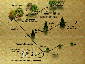
The irrigation components should be assembled as shown in Figure 4. The lateral pipes should be intertwined or “snaked” through the tree lines with about 1 foot extra of polyethylene pipe per 100 feet of tree row. This is done to keep the emitters near the tree when there are changes in air temperature. When the temperature rises, the line will elongate and become longer, but the emitter should not pull away from the tree. The converse is true for colder temperatures. During installation, if the temperature is above normal operating conditions, the emitters should be installed about 6 inches from the tree toward the distal end of the lateral; if it is cooler than normal, install the emitter 6 inches toward the start or fixed end of the lateral.
Emitters are installed in the lateral with a punch tool obtained from the emitter supplier. Specific instructions for each manufacturer should be followed. In some cases, the emitter already is embedded into the drip line. The lateral will become quite warm if it is in sunlight for a period of time. This softens the polyethylene and makes punching clean holes more difficult. The ends of the laterals can be opened to allow cooler water from the supply to offset this problem. The lateral should be flushed to remove any debris that might have accumulated during installation. The lateral usually is filled with water when installing the emitters. The system should be flushed at least twice a year; once before irrigation starts and once after the irrigation season is over. Depending on the system size, usually 30 minutes of flushing will be sufficient. Usually, water flows with approximately 1 foot per second velocity in a pressurized system. If the drip lateral is 600 feet long, the water will move from the filter to the end of the lateral in 10 minutes. However, enough time should be allowed for the system to pressurize (i.e., usually 10-15 minutes). So, in this example, flushing the system for about 25 minutes will be sufficient to remove debris and sediment from the system.
System Operation
Once the system has been designed and installed, proper operation is necessary to get the best service from the system. While there are no absolute guidelines for system operations, general recommendations can be made to improve growth rates of the windbreaks and maintain good system efficiency.
Trees should be planted with adequate soil moisture available. Depending on the location in the state, trees should be irrigated with about 8 to 16 gallons of water per week the first year. Tree plantings in the western parts of Nebraska where precipitation is lower require more water than those in the eastern part of the state. For example, a system with 1 gallon per hour emitters should be run four to eight hours, twice a week. The amount of water should be increased by 2 to 4 gallons per week each year in succeeding years.
Self-flushing emitters will generally not plug, but an inspection to determine if any of the emitters are not working is required for the first few times the system is operated after installation, and periodically after that. The filter should be checked regularly and cleaned.
The weather and type of soil affect the irrigation requirement of trees. Rainfall should be taken into account when deciding if irrigation is necessary. Sandy soils cannot retain moisture as well as heavier soils and must be irrigated more often. Frequent watering of short duration is not desirable for windbreaks because this tends to produce shallow root systems which can be problematic under very windy conditions. Watering twice a week helps the trees develop good root systems, but watering three times a week may be necessary on very sandy soil with trees that are less than three years old.
After the fifth year, trees will be large enough to catch snow to provide moisture for some of their water requirements early in the year. The windbreak should be able to survive on its own after about eight years. By this time, the plants have developed root systems capable of supplying the needed moisture. The irrigations should be discontinued in August to allow the trees and shrubs to “harden off” before winter. The planting should be irrigated once more around the middle of October, after the first freeze, to help prevent winter burn. The time of the last irrigation will vary in different parts of the state, and from one year to another.
It is a good idea to store filters and regulators inside over winter. However, removal and storage of the drip system laterals is not recommended as it would be difficult to realign the emitters with the trees in the spring. The laterals should drain freely, but low spots should be checked to prevent damage due to freezing.
Cost
As a rule of thumb, expect the cost of irrigating a shelterbelt to be approximately $5.25 to $6.50 per tree. The cost will vary with the drip irrigation dealer and will change with the number of trees available to spread the common cost of the supply line. Actual cost ranges for the various components in 2007 are listed below:
- Pressure compensating emitters, 45 cents to 75 cents each.
- Black polyethylene pipe (1/2 or 3/4 inch), 60 cents to 75 cents per foot in 400 foot rolls.
- Pipe fittings, about 45 cents to 65 cents each.
- Sediment filter, $45 to $75.
- Pressure gauge and gate valve, $17 to $30.
- Water supply line, valves, etc., cost will vary.
For additional help or information in designing and installing drip irrigation systems, contact the USDA Natural Resources Conservation Service, or your county extension office. Cost-share on drip systems is available from some Natural Resources Districts and Natural Resources Conservation Districts.
Acknowledgment
The author would like to acknowledge the Extension specialists, Walter L. Trimmer, former district extension specialist; and Brian R. Chandler, district forester, for their work on NebGuide G525.
Visit the University of Nebraska–Lincoln Extension Publications Web site for more publications.
Index: Irrigation Engineering
Irrigation Systems & Development
Issued August 2007


